
Component Identification and Definitions
Relay: A coil of wire wrapped on a ferrous core "Bobbin". A ferrous plate is held above the core of the coil. Attached to the plate are one or more pairs of switch contacts that will change their state of conductivity when current is applied to the coil.
Solenoid: A coil of wire typically wrapped on a plastic "Bobbin" with a hollow center core. A ferrous plunger is drawn into this core when current is applied to the coil. Solenoids act as transducers, converting electrical energy into mechanical energy. The mechanical energy can be used to move playfield features (Slingshots, Flippers, Pop Bumpers) or counting units (Ball in Play, Player Units).
Transformer: Two or more coils of wire wrapped on a ferrous core. Alternating line current on the primary coil creates a magnetic field which is coupled into one or more secondary coils, producing lower, more useable voltages to power lamps, relays and solenoids.
RELAY LOGIC ~ Summary of Operation
Before getting too deep into the physics of Electro-Mechanical assemblies, take a moment and read the instruction card on your machine. These instructions represent some of the unique processes and sequences your machine has been designed to perform. Other processes, such as the start and replay sequences are fairly universal.
Logic is a way of expressing these processes and sequences as a simplified statement. From this statement, electronic circuitry can be designed to represent the conditions required to attain these actions.
EXAMPLE: IF the credit unit is greater than zero AND the ball is in the trough AND the start button is pressed, THEN The machine will start.
In the above example, ALL of the conditions must be met for the event to occur. In logic, this is called an AND function. On a schematic, AND functions appear as a series string of Normally Open (NO) relay contacts.
The second statement describes the replay award:
EXAMPLE: IF the high score level is surpassed OR a playfield special is awarded OR the game over match function is achieved, THEN one credit will be awarded.
In this example, ANY of the conditions can be met for the event to occur. In logic, this is called an OR function. On a schematic, OR functions appear as parallel sets of Normally Open (NO) relay contacts. In application, most logic sequences will be a combination of AND and OR circuitry as well as the NOT function represented by Normally Closed (NC) contacts.
In my opinion, one of the most important steps to resolving logic issues is the understanding of what the sequence of events or conditions are required for a feature to be enabled. Quite often, this feature becomes a single contact set closure in a much larger sequence.
In Solid State machines, this logic is created in the architecture of the circuit boards. Common functions (Coin, Tilt, Start) could be replicated in Hardware, while functions unique to each game would be represented in software (Game ROMs).
Electro Mechanical games of certain eras somewhat follow this standard. Common functions (Coin, Tilt, Start, Score Reels) would have near identical circuitry from game to game, while unique functions would have their own architecture.

With the exception of some playfield solenoid circuits of the late 1970s EMs, all relays and solenoids utilized AC power. The transformer essentially reduced the line voltage (110-120 VAC) into more useable levels. Typically there would be two secondary windings on the transformer, one to provide solenoid power (25-50 VAC) and one to provide lamp power (~6 VAC). From the secondaries of the transformer, schematics were typically drawn so that these "Bus" wires would be perpendicular to the solenoids, lamps and switch contacts.
PINBALL FLIPPER THEORY
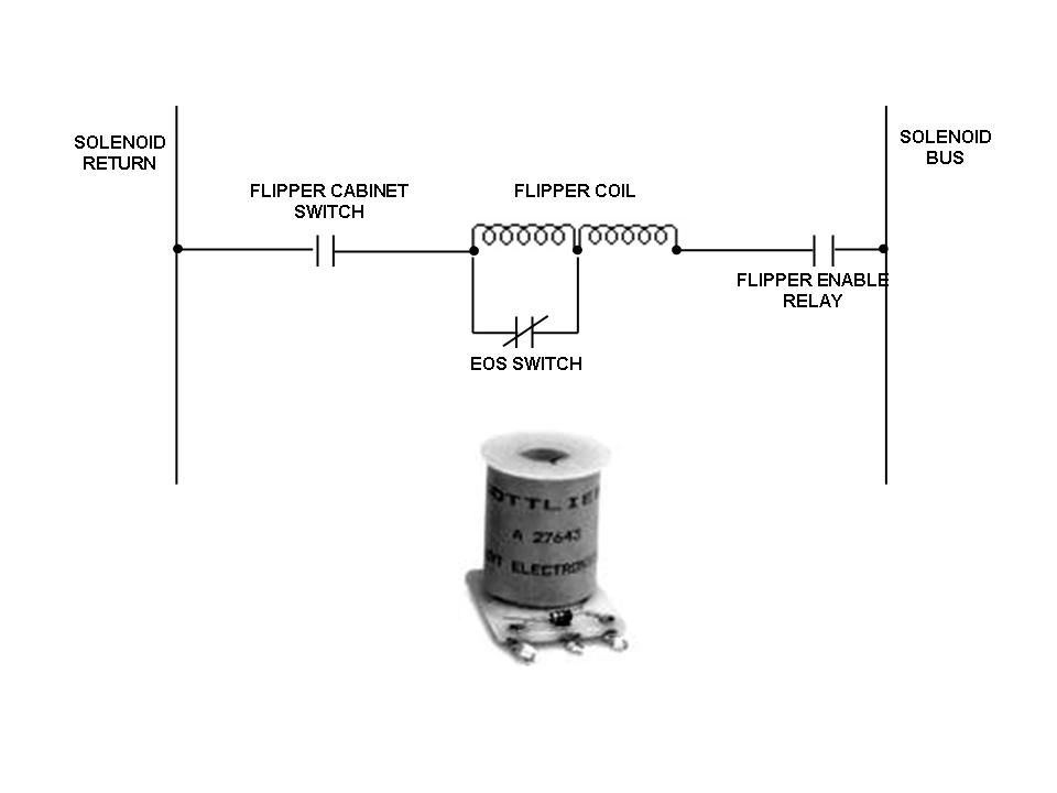
The flipper coil is actually two coils connected in series. One winding is a larger gauge wire and has less turns (less reactance, allowing greater current). The second coil is of a much smaller gauge with possibly nine times as many turns (Much higher reactance, much less current flow). The End of Stroke switch which is normally closed, bypasses the second (Continuous Duty) coil. When you hit the flipper button, you are completing a circuit from the solenoid power supply to the primary flipper coil through the EoS switch and the cabinet flipper switch to ground. Since the second coil is bypassed by the closed contacts of the End of Stroke (EoS) switch, very little resistance is offered, and a lot of current flows, causing the coil to pull in the plunger STRONGLY.
At the end of the mechanisms travel, a bar hits the EoS switch and opens the contacts. This now adds the second coil in series with the first. Far more resistance means far less current, but enough to keep the flipper bat in its upright position (figuratively forever) without melting the coil.
The wiring is fairly universal, regardless of era or manufacturer: The solenoid bus goes to the end terminal with the large gauge wire. The return (the wire headed towards the cabinet flipper switch) connects to the other end terminal with the smaller wire gauge. One side of the EoS switch should connect there as well. The other wire from the EoS switch goes to the center terminal where both windings tie together.
The primary fault that occurs with flipper assemblies is chatter. All problems that could be the cause of this stem from the fact that the current through the coil is not adequate enough to sustain an extended flipper with the EoS Switch no longer shorted.
The top ten reasons (in no particular order) that Flippers chatter:
[1] Secondary winding open
[2] EoS wiring faulty
[3] Coil wired wrong
[4] Coil compromised from previous problems
[5] Return spring too strong
[6] Flipper enable relay contacts dirty or misadjusted (On early Bally SS games, this is the encased relay on the SD board)
[7] Flipper cabinet switch contacts dirty
[8] Cabinet wiring harness connectors not providing clean current path
[9] Low Solenoid Bus Voltage.
[10] (Insert your own discovery here)
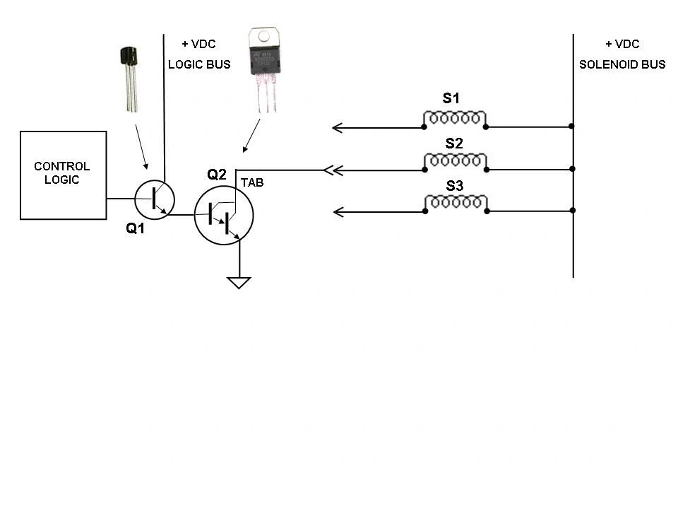
TROUBLESHOOTING SOLID STATE SOLENOID PROBLEMS
|


